RANDOM PAGE
SITE SEARCH
LOG
IN
SIGN UP
HELP
To gain access to revision questions, please sign up and log in.
A2
A Slow But Low Cost ADC
- This type of Analogue to Digital Converter is fairly slow (but cheap and simple).
- It is ideal for data that changes fairly slowly such as vehicle or aircraft control systems.
- Audio signals are also slow enough to be converted.
- To convert video, a flash ADC is needed.
Falstad Simulation
For the Falstad Circuit Simulation, CTRL+Click Digital Ramp ADC
In options, check European Resistors and uncheck Conventional Current.
Adjust the slider to change the analogue input voltage.
Alternatively view Digital_Ramp_ADC.txt.
Save or copy the text on the web page. Import the saved or copied text into the Falstad simulator.
Here is the new HTML5 Simulator Site.
The Circuit

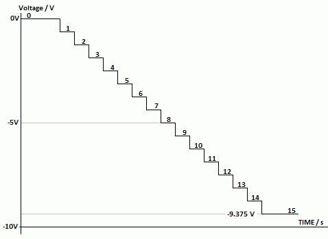
- The output of a binary counter is connected to a DAC.
- This produces a ramp wave.
- A comparator is used to compare the ramp with the signal to be converted.
- When the comparator changes state, the binary data is latched.
- In this way the analogue input is converted to binary numbers.
- The diagram below shows a 4 bit ADC. 8, 12 and 16 bit converters are more common.
| 8 |
4 |
2 |
1 |
|
| 0 |
0 |
0 |
0 |
0 |
| 0 |
0 |
0 |
1 |
1 |
| 0 |
0 |
1 |
0 |
2 |
| 0 |
0 |
1 |
1 |
3 |
| 0 |
1 |
0 |
0 |
4 |
| 0 |
1 |
0 |
1 |
5 |
| 0 |
1 |
1 |
0 |
6 |
| 0 |
1 |
1 |
1 |
7 |
| 1 |
0 |
0 |
0 |
8 |
| 1 |
0 |
0 |
1 |
9 |
| 1 |
0 |
1 |
0 |
10 |
| 1 |
0 |
1 |
1 |
11 |
| 1 |
1 |
0 |
0 |
12 |
| 1 |
1 |
0 |
1 |
13 |
| 1 |
1 |
1 |
0 |
14 |
| 1 |
1 |
1 |
1 |
15 |
The ramp is this way up because the summing amplifier used in the DAC is also an inverting amplifier.
Ramp ADC Problems
- There is a time delay after the start pulse because the counter has to reach the correct value.
- When the comparator changes state, the conversion is complete.
- This could happen quickly or take longer if most of the ramp has to be compared.
- The delay depends on
- the clock speed and
- the value of the data input.
Typical ADC Chips
All the components above are built into one chip. This has pins to ...
- SC - start the conversion
- EoC - signal the end of conversion.
- During the conversion, the output is not valid.
- The EoC (end of conversion) signal indicates when the conversion is complete.
- OE - enable the output. This is tristate logic. When the output is enabled, the ADC data can be copied to the data bus.
reviseOmatic V3
Contacts, ©, Cookies, Data Protection and Disclaimers
Hosted at linode.com, London


